Tetrahedral Vs. Hexahedral Mesh (Mesh Comparison)
- As we know that the accuracy of CFD simulation highly depends on mesh quality. If mesh quality is not good but the solution procedure is carried out in the best way, then it may be possible to achieve an inaccurate result. No one mesh type is universally acceptable. The accuracy of different types of mesh depends on the model or object which is to be analyzed. Different mesh types give different results. There are many mesh types available is Ansys fluent. Here I did a little comparison between tetrahedrons ( Unstructural mesh ), hex dominant ( Structural mesh ) and hex prism mesh, and analysis carried out is velocity analysis at the outlet of pipe, pressure analysis at the outlet of pipe, and temperature analysis on the wall of the pipe. Note that analysis is done in ‘fluent’ software.
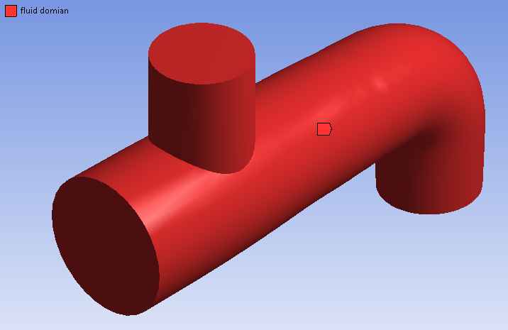
- First of all, I create simple geometry as shown in fig below…
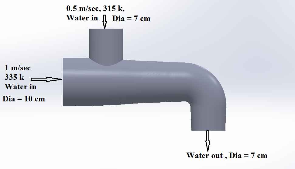
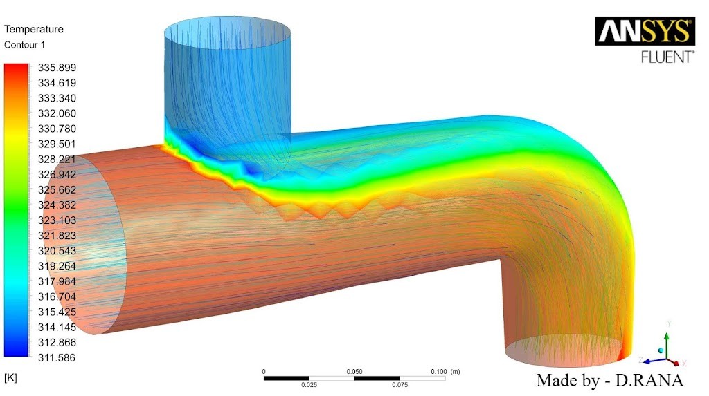
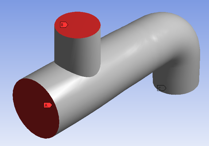
- Geometry has 2 inlets, inlet-1, and inlet-2 has a diameter of 10 cm and 7 cm respectively. Inlet velocity at inlet-1 is 1 m/sec with temperature 335 k and inlet velocity at inlet-2 is 0.5 m/sec with a temperature of 315 k. The outlet diameter is 7 cm. For simply understanding, all parameters are indicated in the above fig.
After that, I created different types of mesh ( tetrahedrons, hex dominant, hex prism ) shown in fig below.
Tetrahedral mesh

 |
| cross-section of object |
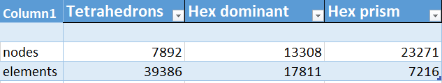
Number of nodes = 7892
Number of elements = 39386
People also search – What is ultrasonic testing in NDT and welding
Hex dominant mesh

 |
| cross-section of object |
Number of nodes = 13308
Number of elements = 17811
Hex prism mesh

 |
| cross-section of object |
Number of nodes = 23271
Number of elements = 7216
While generating the above mesh, the following parameter is taken.
- Physics preference = cfd
- Solver preference = fluent
- Element order = liner
- Mesh size = 10 mm
- Use adaptive sizing = No
- Growth rate = Default (1.2)
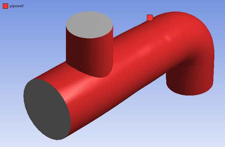
After mesh generation, the boundary name is assigned and the fluid domain is created.
After creating a fluid domain and applying name selection, the setup is done. While the setup of above mesh, the following parameter is taken.
- Gravitational acceleration = -9.81 m/s2 ( negative Y – axis)
- Model = energy equation is on and the laminar model is taken.
- Fluid material = water-liquid
- Boundary condition = at both inlet ‘velocity inlet’ boundary condition is taken. at outlet ‘outflow’ boundary condition is taken. at the pipe wall ‘wall’ boundary condition is taken.
- Solution method = SIMPLE ( Semi Implicit Method for Pressure Linked Equation ) algorithm which is widely used in the numerical procedure to solve Navier stokes equations.
- Residual = 1 * e-3
After setup and solution of above three mesh ( Tetrahedrons mesh, Hex dominant mesh, Hex prism mesh ) result is obtained which is shown below.
Tetrahedral mesh
Number of nodes = 7892
Number of elements = 39386
Max. velocity at outlet = 3.104 m/s
Min. velocity at outlet = 0.40 m/s
Max. pressure at outlet = 98503.715 pascal
Min. pressure at outlet = 96786.536 pascal
Time for first 1000 iteration = 2 min 52 sec
Hex dominant mesh
Number of nodes = 13308
Number of elements = 17811
Max. velocity at outlet = 3.327 m/s
Min. velocity at outlet = 0.274 m/s
Max. pressure at outlet = 98568.914 pascal
Min. pressure at outlet = 95289.477 pascal
Time for first 1000 iteration = 1 min 55 sec
Hex prism mesh
Number of nodes = 23271
Number of elements = 7216
Max. velocity at outlet = 3.384 m/s
Min. velocity at outlet = 0.705 m/s
Max. pressure at outlet = 98358.895 pascal
Min. pressure at outlet = 95431.598 pascal
Time for first 1000 iteration = 1 min 5 sec
People also search – Heat Transfer Of Radiation
Conclusion
I already mentioned that no one mesh type is universally acceptable. The reliability of the mesh depends on the object or model which is to be analyzed. Here I have done little experiment between the above three mesh types and the result obtained is related to the above geometry.
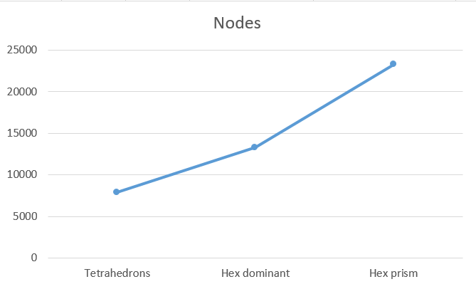
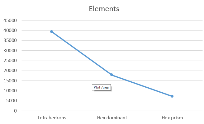
- Another thing is to conclude that mesh with more number of elements takes more time to converge. For example, the tetrahedral mesh has 39386 element which is the highest element compared to the remaining two mesh, and tetrahedrons mesh take more ( 2 min 52 sec ) time to converge the solution. Other hands, hex prism mesh have less no. of elements (7216) but it has the highest number of nodes, and the time required to converge the solution is 1 min 5 sec because of less no. of elements. The above fig shows a graphical representation of nodes and elements. From the graph, it is concluded that mesh which has less no. of node, has more no. of the element, and mesh which has more no. of node, have less no. of the element.
- Finally from the CFD result, For faster CFD simulation, hex prism mesh can use. But if you do not have time constrain then the tetrahedral mesh is good and gives a better result.
Result of analysis