What is a centrifugal pump?
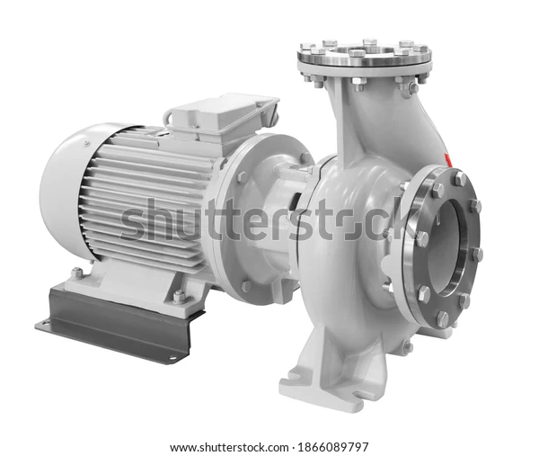
The pump is a device that is used to transfer the fluid from one place (low-pressure side) to another place (high-pressure side).
In a centrifugal pump, the fluid enters the center of the pump impeller along the axis of the rotating shaft, fluid accelerates by the impeller and leaves radially outward into the volute chamber by the action of centrifugal force.
Centrifugal pump working principle
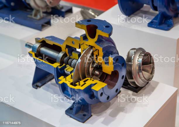
The Centrifugal pump is similar to the reverse Francis turbine. In the Francis turbine, the liquid comes radially and leaves axially. While in the centrifugal pump, the liquid comes axially to the shaft and leaves radially to the shaft axis. The Centrifugal pump works on the principle of forced vortex flow. The Centrifugal pump impellor is connected with an electric induction motor by a shaft, which converts electrical energy into mechanical energy. This mechanical energy is used the drive the pump. The pump increases both kinetic energy and hydrodynamic energy (pressure energy) by converting the mechanical energy. The centrifugal pump transport fluid by converting mechanical energy into kinetic energy and hydrodynamic energy (pressure energy).
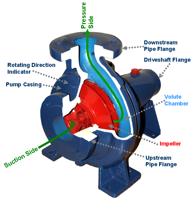
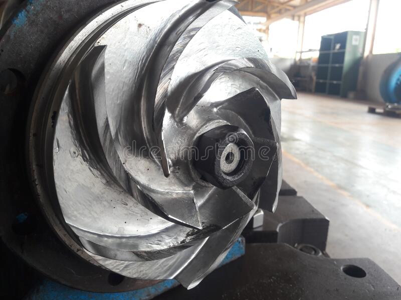
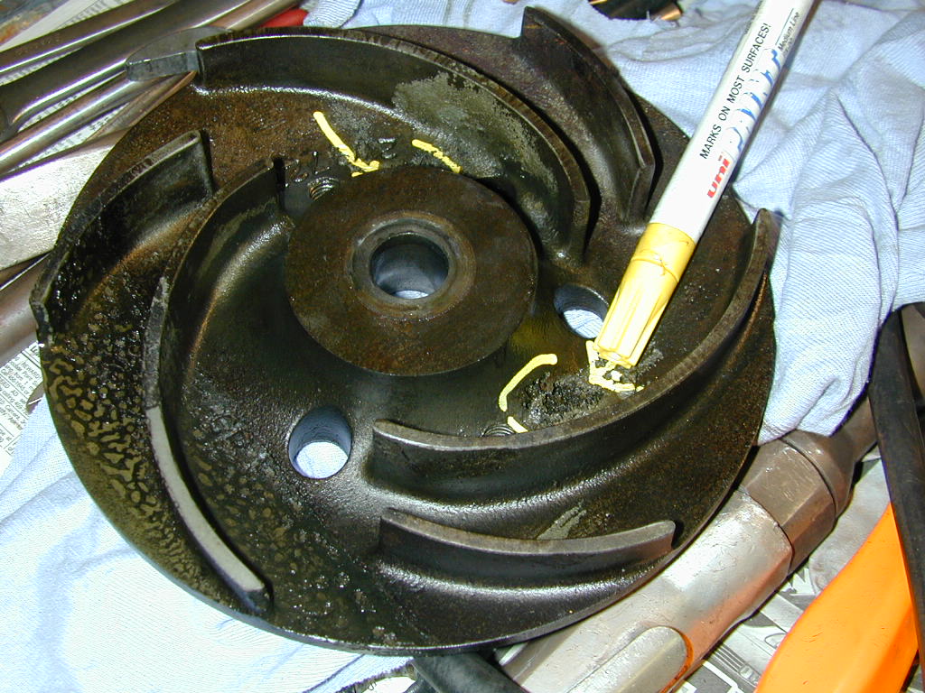
The impeller is the heart of the pump. The impeller has a series of curved vanes fitted inside plates. The impeller is always submerged in water. When the impeller is rotated, it makes the fluid (liquid or gas) surrounding it also rotates. As the fluid rotates, the fluid is radially pushed outward in all directions to the end edge of the impeller vanes by the action of centrifugal force and the fluid is go towards the discharge side. At the discharge side of the impeller, both kinetic energy and pressure energy of water will rise.
As the fluid (water) moves from the center of the impeller to radially outward, the negative pressure will be induced at the eye of the pump impeller. Such a low pressure helps in sucking fresh water into the pump continuously.
The water enters from the eye of the impeller, going or trapped between the vanes. As the impeller rotates, it imparts kinetic energy to water and increases the velocity of the water. With this high velocity, the water is strike the wall of the pump casing and water is starting collecting in the volute chamber. As the water collects in the volute chamber, it slows down and the kinetic energy of water starts converting into the pressure energy. The flow of water remains continuous behind this. This maintains the pressure as well as the flow rate of water in the pump and allows the water to be pushed through the pipes.
Why priming is required in the centrifugal pumps?
Priming is the method of removing air (low density fluid) from the pump and this can be done by adding water manually. This removes all air from the pump. Now, The pump impeller is fully submerged by the high density fluid (water) and the required pressure will be generated. This is the reason why priming is important for centrifugal pumps.
If there is no water present initially. Then, at the eye of the impeller, the negative pressure developed by the rotating air will not able to suck the fresh stream of water.
What is cavitation in a pump?
We know that, as the pressure decreases, the boiling point of water also decreases. The water will start to boil at a low temperature.
In the case of a centrifugal pump, there is low pressure at the eye of the impeller. If this pressure is less than the vapor pressure of water then water will start to boil at a low temperature. This will form a bubble of water and spoil impeller materials over a period of time. This phenomenon is known as cavitation.
During cavitation, the water bubble will burst. Due to that, the water will rapidly strike the wall of the casing which removes a very little amount of material from the surface of the casing. If these phenomena remain continuous then, over a long period of time, the wall of the casing will be completely damaged and there will be a possibility to small holes are likely to fall on the surface of the pump casing. In a centrifugal pump, cavitation is reduced by the maintaining available pressure at the inlet must be greater than the NPSH value.
Centrifugal pump application
- Centrifugal pumps are used in the refineries, oil and gas industries for pumping oil, slurry, and mud.
- Centrifugal pumps are used in industrial and fire protection for ventilation, heating, and air conditioning, for boosting the pressure of a fluid, and as a boiler feed pump.
- It is also used in agriculture, irrigation, waste management, In wastewater processing plants, gas processing, municipal industry, and drainage.
- In sewage applications, It is used to drain the sewage and slurry.
- It is used in food industries like dairy industries to transfer milk and milk products.
- In cosmetics and pharma industries transfer hydrocarbons, lactose, paints, cellulose, petrochemical, glucose, beverage production, and many others.
what is the characteristic curve or diagram of a centrifugal pump? what do these pump diagrams represent?
In centrifugal pump performance curves, the vertical Y-axis represents the pressure head in meters or feet and the horizontal X-axis represents the flow rate is how much water the pump can push in unit time.
Assume that the pump is pushing the liquid horizontally. So, there is no pressure head and the water is flowing at its maximum flow rate at a point-A.(see the below pump diagram). Now suppose we start the gradually increase the pump head. We can see the flow rate decreases but the pressure increases. That’s because the water is now pushing against gravity and the friction.
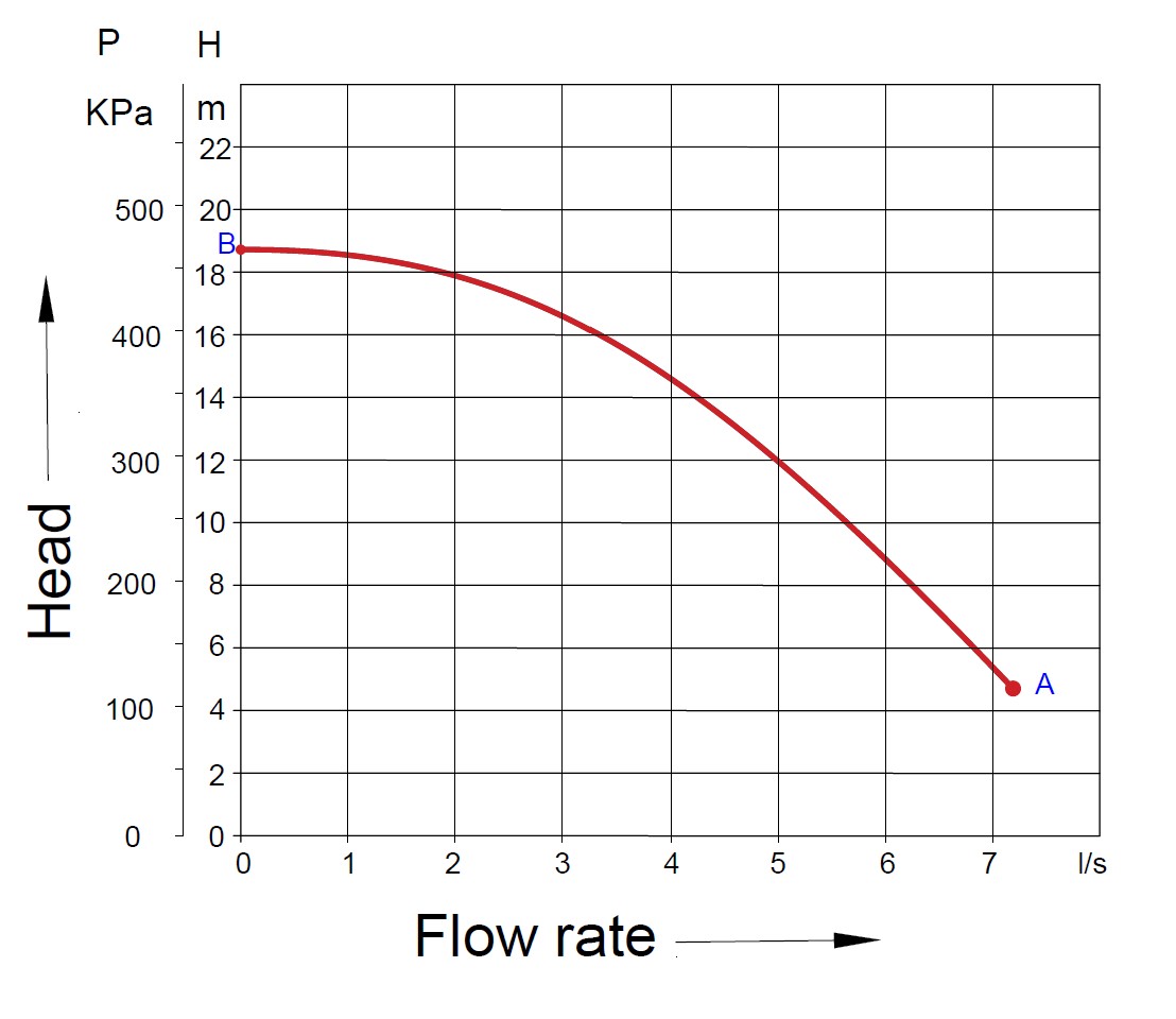
Suppose we keep the pump remaining ON to the vertical position. In that case, there will be one specific height will come at which there is zero water flowing out of the pump but maximum pressure and that’s because the centrifugal pump uses all its energy to push against the water and hold it as high as it possibly can within the pipe. In the centrifugal pump performance curve, point-B is a maximum head up to which the centrifugal pump can push the water.
Pump head
In the centrifugal pump performance curve, the pump head is represented on a vertical Y-axis. A pump head is a height at which a pump can push or raise the water against the gravity within a pipe. Head is related to the pressure so sometimes we talk about the term pressure head or head pressure. The pump head or head pressure is measured in feet or meters.
Now, you are thinking that why head pressure is measured in feet or meters? Especially as you see the pressure gauges on the pump generally reading bar or psi.
The reason behind it is that the pump manufacturers are only in interested knowing how high their pump can push a liquid. They do not interested to know which liquid your system will be pumping.
For example, the pump which can provide 125 feet of the head can pump the liquid nearby 125 feet. It doesn’t care which liquid it is pumping.
During the flow within a pipe, the pipe wall friction or friction generated by pipe fitting (Tee, Cross, Elbow, Reducer) will try to restrict the flow. This causes pressure losses which wastes energy from the pump. The amount of friction depends on the pipe materials, the surface roughness of the inner wall as well as liquid type. To fulfill our requirements, we need to calculate how much pressure loss or friction will generate and ensure that the pump we select can overcome this otherwise there will be no liquid out the upper end. The amount of friction loss within a pipe can be calculated by the “Darcy-Weisbach equation“
Flow rate
The flow rate in the centrifugal pump performance curve is represented on a horizontal X-axis. The flow rate is a measurement of how much liquid is flowing from the pump in a given amount of time. This flow rate is estimated in many different units for example liter per second, cubic meters per hour, or gallons per minute.
Centrifugal pump performance curve
The pump manufacturer will test each pump to obtain the performance data and then plot this on the graph. This centrifugal pump performance curve will represent all the possible configurations between head pressure and flow rate. We use this to check whether our pump will suit our requirements. As you can see in the performance curve, the flow rate increases the head pressure decreases. The pump will be considered if our system requirements are on or below the performance line.
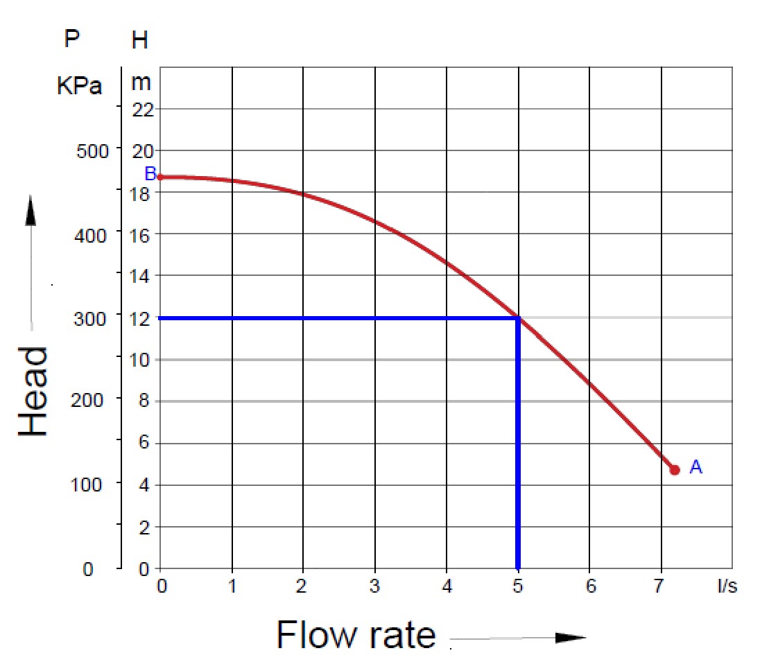
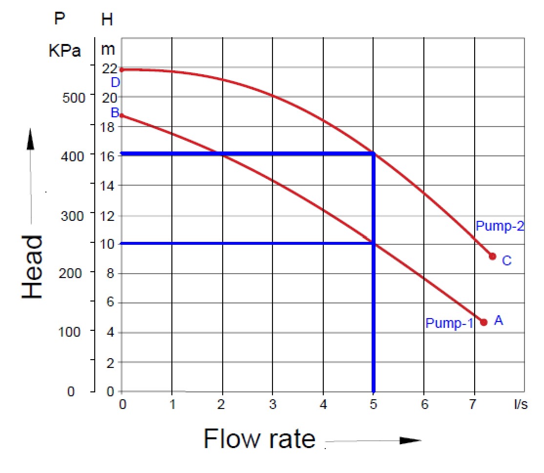
Let’s take an example, based on the above centrifugal pump diagram or performance curve, if we need to deliver the water 12 meters up from the ground then from the centrifugal pump performance curve (above pump diagram), the pump with 5 liters per second has a head nearby 6 meters i.e the pump can push the water at required height with specified flow rate. As long as our system requirements are on or below the performance line, the pump can be considered. Let’s take one more example, there is a centrifugal pump diagram of two pumps plotted on a graph. We need a flow rate of 5 liters per second with a head above 15 meters. That means the pump-1 (10 meters of head) can’t be used as the operating point of pump-2 (16 meters of head) is above the performance ability of the pump-1.
Impeller size on centrifugal pump diagram
The impeller diameter will change how much water can be moved i.e it will change the flow rate. so on some centrifugal pump diagrams, we will see multiple Centrifugal pump performance curves which will give us the performance details of the pump for different diameter impellers.
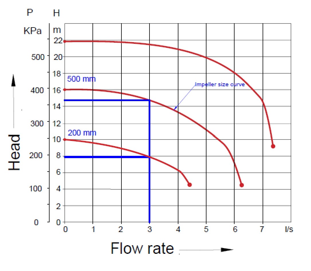
For example, from the above centrifugal pump diagrams, look for a flow rate of 3 liters per second, the 200 mm diameter impeller gives us 8 meters of the head but if we use the 500 mm impeller then we would get nearby 15 meters of pump head.
Pump power on centrifugal pump diagram
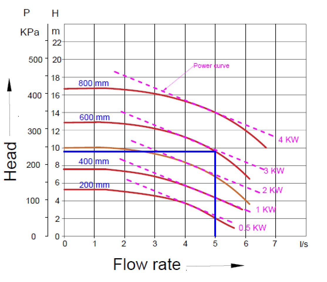
The centrifugal pump manufacturers will generally provide a chart that plots the power requirement. For example, if we needed 5 liters per second flow rate with nearly 10 meters of the head then the power required to run the pump is between 3-kilowatt (see below centrifugal pump diagram). we’ll have to use a 3-kilowatt motor and we see the performance curve falls completely under this line.
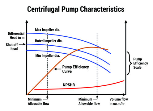
Pump efficiency on the centrifugal pump performance curve
The centrifugal pump performance curve also represents the efficiency data of the pump measured in percentage. From the below centrifugal pump diagram, the curve line represents the efficiency of the pump where the pump increases up to its maximum efficiency, and then it starts to decline again. The efficiency decreases as the impeller size decrease. This is because the gap between the pump casing and the impeller increases and that will generate less centrifugal force to push out the water.
There are always some power losses during the transmission through the couplings, bearings, shaft, seals, cooling fan etc .
For example, on the centrifugal pump diagram, we can see that if the pump provided 125 gallons per minute at 25 feet of the head then it would run at around 67% efficiency which isn’t very good if the same pump operating at 30 feet of head for 138 gallons per minute then it would run at nearby 73% efficiency which is much better.
NPSH on centrifugal pump diagram
The NPSH is the minimum pressure that must be available in the suction inlet of the pump to avoid cavitation. NPSH (Net Positive Suction Head) is the margin of pressure over vapor pressure at a pump inlet (suction) side. NPSH is the difference between suction pressure (stagnation) and vapor pressure. In equation form:
NPSH = Ps ‑ Pvap
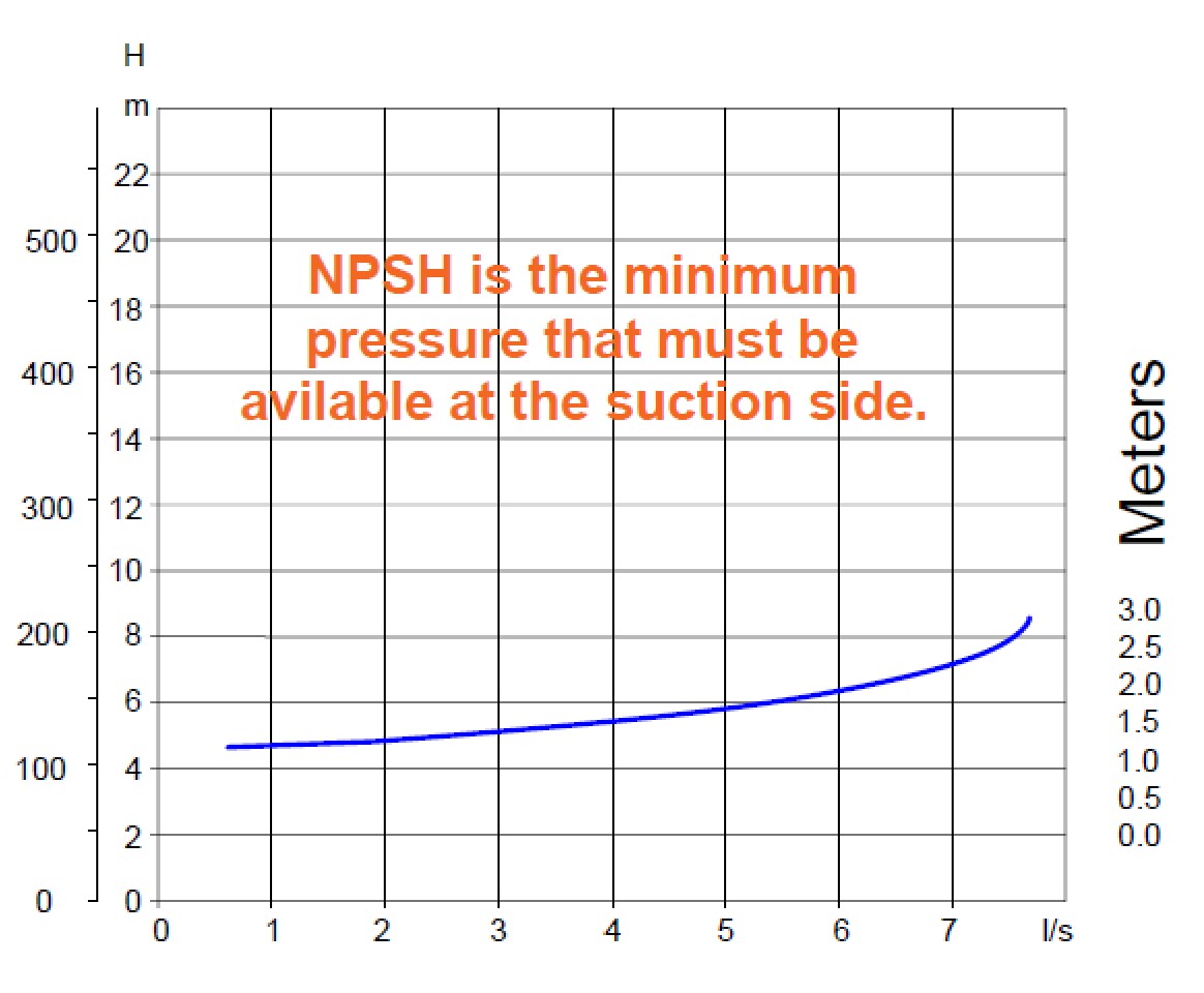
The NPSH usually has an upward curve which means as the flow rate increases, the value of NPSH also increases. It is measured in meters or feet sometimes kiloPascals. To avoid cavitation, the available pressure at the inlet must be greater than NPSH. For example, if we were to move 4 liters per second then we would require an NPSH value of around 1.5 meters.