Sphere Of Influence, Bias And Bias factor, Types of Meshing In Ansys
The following local mesh controls are available in Ansys meshing:
(1) Method Control
(2) Sizing Control
(3) Mapped Face Meshing Control
(4) Contact Sizing Control
(5) Match Control
(6) Pinch Control
(7) Refinement Control
(8) Inflation Control
(9) Gap Tool
 |
| various option for local mesh controls in Ansys |
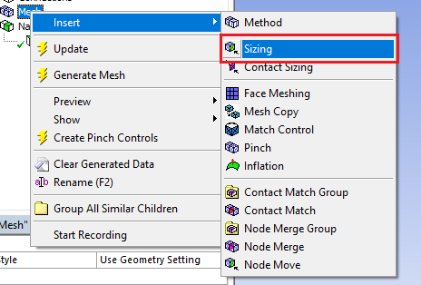
You can control your local mesh by just right click on Mesh option from tree outline > insert .
Method Control
Diffrent types of Meshing in Ansys
1.Automatic Mesh
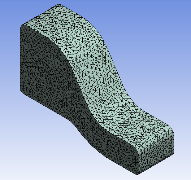
2. Tetrahedrons Mesh
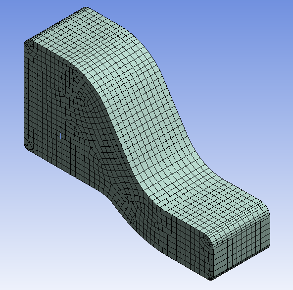
3. Hex dominant Mesh

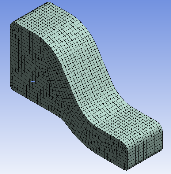
4. Sweep Mesh
5. Multizone Mesh
6. Cartesien Mesh

7. Layerd Tetrahedron Mesh

Sizing Control
- The element size for a selected body, face, or edge.
- The number of divisions along an edge.
- The modification in element size by using “Sphere of influence”
The basic steps for using the local Sizing control are presented here.
There are 4 types of local sizing :
(3) Edge Meshing or Defining Local Mesh Sizing on a Edge
(4) Vertex Meshing or Defining Local Mesh Sizing on a Vertex
(1) Face Meshing or Defining Local Mesh Sizing on a Face :
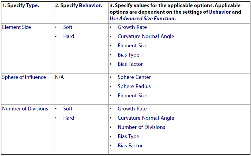
The following table gives information or overview of how to define face meshing or local mesh sizing on a face.
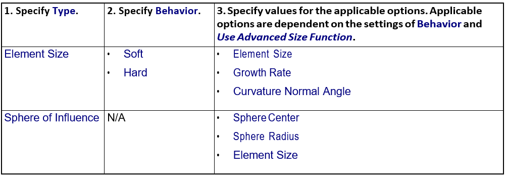
(1) Specify type :
Element size
Element size is a size of the element or mesh. By using element size, you can create mesh as per your sizing requirement.
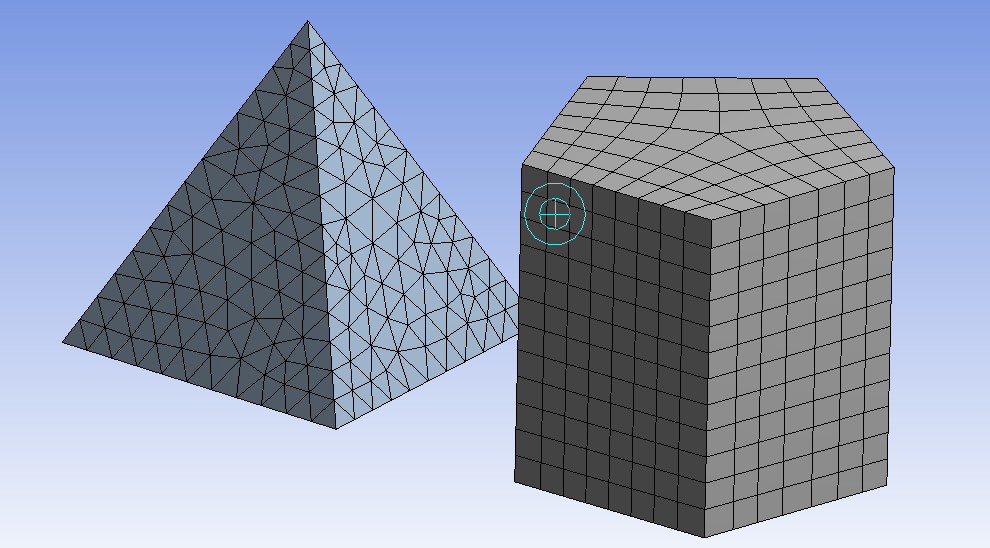
Sphere of Influence meshing in Ansys
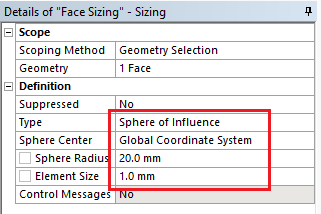
- Sphere of Influence is an available option in the Type field if you selected a body, face, edge, or vertex and ‘Use Advanced Size’ Function is off. Sphere of Influence behaves as a Hard setting. The Sphere of Influence modify pre- existing sizing(mesh) which is inside a sphere.
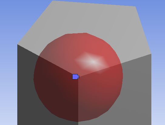
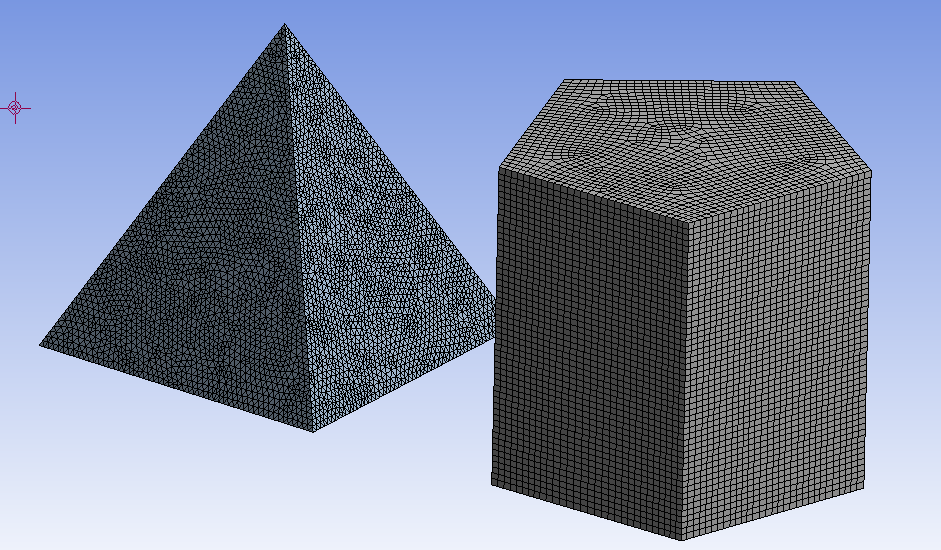
- In Sphere of influence, you can create sphere by using local coordinate system whose origin is to become the center of the sphere or by enter the radius of the sphere in the ‘Sphere Radius’ field. Enter a value in the ‘Element Size’ field. The element size will be applied to area which is covered in the sphere.
 |
| Sphere with radius = 20 mm |
 |
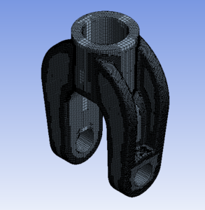
| Sphere of Influence mesh with sphere radius 20 mm |
(2) Specify Behavior :
If Use Advanced Size Function is on:
• Choosing the Hard option for edges means that the size or number of divisions is fixed on the edge and cannot be changed by the meshing algorithm and the probability of a mesh failure increases.
Growth Rate :
- The Growth Rate is the same as that of the global growth rate that you can set in the Details View when the Mesh option is selectedin the Tree Outline.
- Growth Rate represents the increase in element edge length with each next layer of elements. For example, a growth rate of 1.2 results in a 20% increase in element edge length with each next layer of elements.
- It is available when Use Advanced Size Function is on. For Growth rate, Specify a value from 1 to 5 or accept the default. The default is calculated based on the values of the Relevance options.
- Curvature Normal Angle is the maximum allowable angle that one element edge is allowed to span another element edge. You may specify Curvature Normal Angle for a entity like body, face, or edge only.
- Curvature Normal Angle is Available only when ‘Use Advanced Size’ Function is set to either ‘On: Proximity and Curvature’ or ‘On: Curvature’. You can specify a value from 0 to 180 degrees to override the global setting.
The parameter like growth rate, element size, curvature normal angle has same meaning for all (Face, Body, Edge, Vertex) type of sizing.
(2) Body Meshing or Defining Local Mesh Sizing on a Body
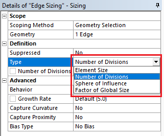
(3) Edge Meshing or Defining Local Mesh Sizing on a Edge :
The following table gives information or overview of how to define edge meshing or local mesh sizing on a edges.
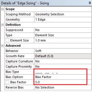
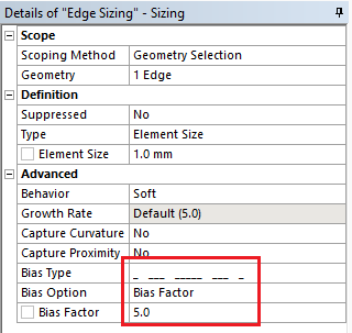
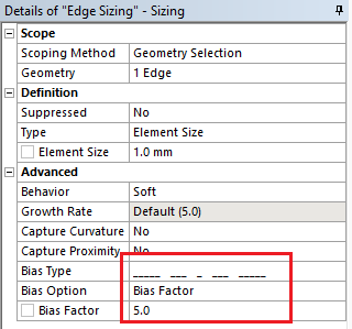
Bias type and Bias factor in Ansys meshing:
Bias Factor is defined as the ratio of the largest edge to the smallest edge. For edges only, use Bias Type to adjust the spacing ratio of nodes on an edge.
This feature is useful for any engineering problem where nodes need to be clustered on an edge or group of edges. There are 4 pre-determined patterned options available in ANSYS workbench as shown in fig.

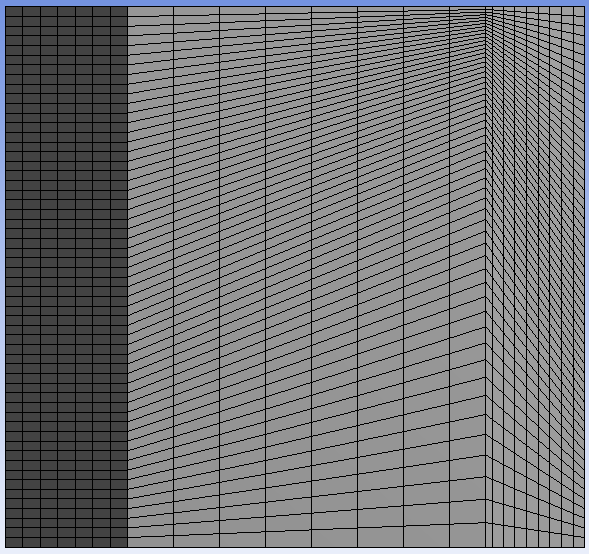
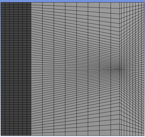
As the bias factor increase, the mesh becomes more finer and finer according to whatever pattern you choose. Here shows various types of bias patterned meshed in ANSYS workbench.


 |
| Bias factor=5 |
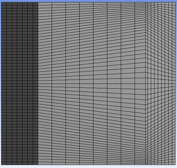
 |
| Bias factor=10 |
Please note the bias type marked in red box in image.
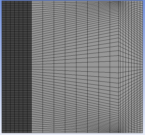
 |
| Bias factor=5 |
 |
| Bias factor=10 |
And last pattern…
 |
 |
| Bias factor=5 |
 |
| Bias factor=10 |
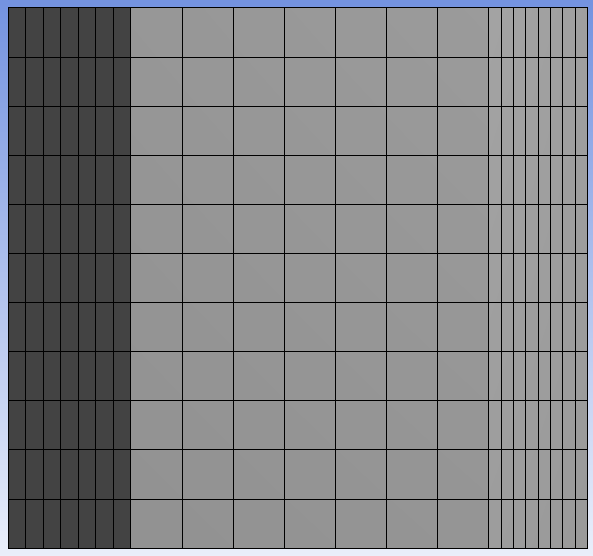
Number Of Division :
If you want to divide the edge in specific no. of part then this feature is help you. just specify no. of division as per your requirement.
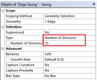
 |
| No. of division = 10 |
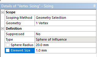
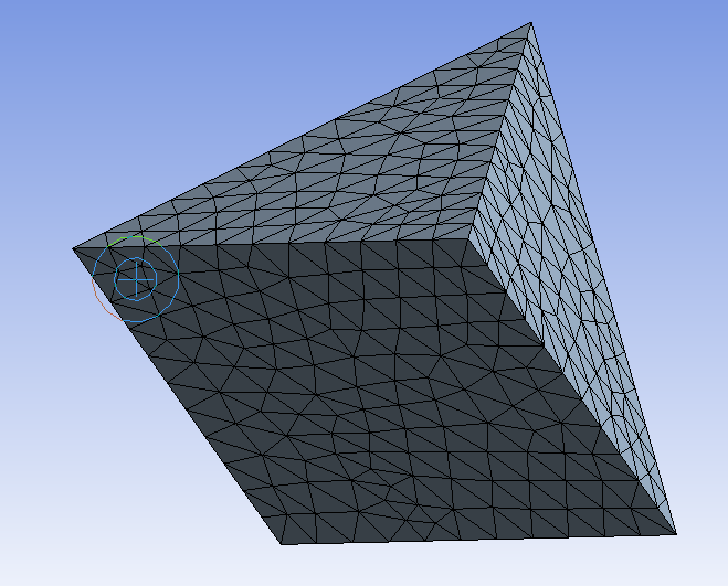
Vertex Meshing or Defining Local Mesh Sizing on a Vertex :
The following table gives information or overview of how to define vertex meshing or local mesh sizing on vertex.

Here the center of sphere is whatever vertex you select as show in fig.