Ultrasonic testing
The ultrasonic testing is non-destructive testing, which means we are not going to harm our materials or we are not going to destroy our materials, and here from the name itself, you can understand that we are using the ultrasonic waves to conduct the examinations and make the measurements.
what is the ultrasonic wave?
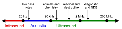
Ultrasonic waves are high-frequency and inaudible sound waves that have a frequency more than 20KHz.
 what is the ultrasonic wave? Source – Wikipedia
You can see the above chart that below 20 Hz we are calling it infrasound. From 20 Hz to 20 kHz it is acoustic range. within this range, the human ear can able to hear and above 20 kHz, it is an ultrasonic sound that has a higher frequency and generally that higher frequency we are using for the non-destructive testing.
Properties of ultrasonic waves
The ultrasonic waves are no different from normal sound in their physical properties except in that humans cannot hear them. It is beyond our human audible capacity.
They have the following properties.
- The Ultrasonic waves cannot travel through the vacuum, so they always need some media.
- Their velocity mainly depends on the density and young modulus of materials.
- They are reflected and refracted just like the light waves.
- The Ultrasonic waves travel with the speed of sound in a given medium.
- The speed (velocity) of ultrasonic waves is more in more dense media. For example, for air, the velocity of ultrasonic waves is 330 meters per second, for water, it is around 1480 meters per second, and for steel, it is 5920 meters per second. So in that case you can see that when you are talking about the solid that is like steel the ultrasonic wave’s velocity is more.
Principle of the Ultrasonic testing
How does ultrasonic testing work?
A pulser or receiver is an electronic device that is used to produce high voltage electrical pulses. The transducer generates high-frequency ultrasonic energy which is driven by the pulser. The ultrasound sound or energy is generated and raised through the specimen or material in the wave’s form. When there is a discontinuity, such as a crack, in the way path, part of the energy or ultrasound will be reflected back from the flawed surface, otherwise, it will go through the material or substance itself.
Ultrasonic Transducers are also called the probe which generates and receives an ultrasound of all frequencies and intensity. For discontinuity (cracks, holes, etc.) detection, Probs or transducers come in a wide variety of sizes, case styles, and frequencies but most have a common internal structure. It is important to choose the proper size, desired bandwidth, and frequency for a given application.
Use of couplant materials
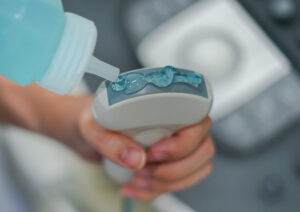
Couplant materials are generally a liquid used for easy transmission of ultrasonic waves or energy from the transducer into the test material or specimen. The use of couplant is necessary due to the acoustic fluctuations mismatch between test specimen and the air is large. To avoid this, we are using some gel kind of materials, so that, the ultrasonic wave directly passes through the specimen or material. So the couplant replaces the air and makes it possible to get the majority of sound energy into the test specimens so that a useable ultrasonic signal can be obtained.
Working Principle of the Transducers
The active element of the transducers is a thin disc of piezoelectric ceramics or piezo composite that works on the phenomenon of piezoelectricity. So generally we are using some kind of crystal kind of things over there.
What is Piezoelectricity or the piezoelectric effect?
- When crystals of some materials are subjected to mechanical pressure in a certain direction, charges of opposite signs develop to their faces, normal to the direction of the applied pressure. This behavior is known as the piezoelectric effect. It is a reversible process that means, electrical signals can be converted into mechanical vibrations and vice versa.
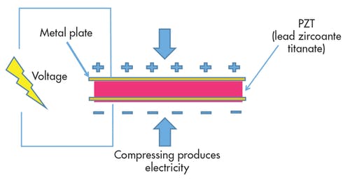
- Piezoelectric crystals are combinations of negative and positive ions in an alternating fashion. Tensions and compressions push and pull these positive and negative ions away from each other, creating an energy gradient across the crystal and allowing an electric current to flow and it will generate the mechanical vibrations.
Classification of the ultrasonic transducer
The piezoelectric ultrasonic transducer can be classified on the basis of beam orientation, on the basis of coupling media, on the basis of no. of elements, and in other ways. Some of the most common classifications are explained below.
Classification of the ultrasonic transducer on the basis of beam orientation
Normal beam ultrasonic transducer
As the name suggests, the normal beam ultrasonic transducer transmits the ultrasonic waves normal to the face of the transducer as shown in the image
Angle beam ultrasonic transducer
As the name suggests, the angle beam transducer transmits the ultrasonic waves at an angle other than normal. The required transmission angle is obtained by attaching the wedge ( made of plastic ). The wedge angle is designed to operate the probe between the first and second critical angles.
Angle beam ultrasonic transducer is used when scanning is not possible to normal to the surface of the specimen.
Classification of the ultrasonic transducer on the basis of the coupling mechanism
Contact ultrasonic transducer
The transducer operates by bringing direct contact between the test specimen and the transducer. While using this transducer, some dry couplent or such kind of liquid is required to proper propagation of ultrasonic waves from transducer to test specimen.
Immersion transducer
Immersion transducer fully immersed in a fluid typically water. The ultrasonic waves are transferred from the transducer to test specimen through the water
Air coupled transducer
For more information “Air coupled ultrasonic transducer“
Classification of the ultrasonic transducer on the basis of a number of elements
Single element ultrasonic transducer
This transducer contains only a single active ceramic element that transmits and receives the ultrasonic waves. Hence the single element transducer has a simple design which results in low cost. Of course, if we increase the number of elements the design will be complex, and also cost will increase.
Double/dual element transducer
- Double element ultrasonic transducer has two separate elements, one for transmission and the second for the receiver of the ultrasonic waves, housed in a single common case.
- This transducer can provide a more accurate result near the surface because the transmission element only transmits the ultrasonic waves and the receiver element only receives the ultrasonic waves from the test specimen. Due to this, there is no ultrasonic sound or wave interference during the transmission and receiver as it is happening in single-element transducers.
- But due to the arrangement of two elements in one compact case, the design will be complex and costly compared to the single element ultrasonic transducer.
Different testing methods to carry out ultrasonic testing in ndt
Ultrasonic testing can be carried out in many different ways. The selection of a specific test method depends on the manufacturing process of the product, geometry, nature of the product, and availability of scanning area.
Classification of the ultrasonic testing in ndt to carry out ultrasonic testing.
(1) Normal beam and angle beam test technique
- This method relates to the angle that ultrasonic waves or energy enters in the test specimen
(2) Immersion and contact technique
- These methods are related to the coupling method from the transducer to the test specimen.
(3) Pulse echo and through transmission technique.
- This method is related to transmitted and reflected energy.
Normal beam and angle beam test technique external link
Immersion and contact technique
Immersion technique
In this technique, the transducer and test specimen are fully immersed in a water bath. This arrangement allows frictionless, better movements of the ultrasonic transducer while maintaining steady coupling (water). Immersion technique carried out automatic scanning with high speed with efficient crack detection.
Contact mode technique
In this technique, the ultrasonic transducer is kept in physical contact with a test specimen by the couplent during the inspection. Water, glycerine oil, or some gel kind of thing is used as a couplent between a test specimen and an ultrasonic transducer.
The contact mode technique is generally used for manual inspection.
Pulse echo and through transmission technique.
Pulse echo technique
The pulse of ultrasonic waves is transmitted by the ultrasonic transducer into the test specimen. The ultrasonic waves are entered from the top and reflect back from the bottom if there are no cracks or discontinuity and produce echo on the CRT screen.
Now, if there are any cracks or discontinuity at a midway of the test specimen, ultrasonic waves are reflected back from the cracks and produce an echo in between transmission echo and receiver echo as shown on the CRT screen.
The CRT screen is calibrated in terms of the size of the specimen and the amplitude of ultrasonic waves. The location and size of cracks are displayed in terms of amplitude and calibrated properly on the CRT screen.
Through transmission technique
In this technique two separate transducers one is a transmitter and the second is the receiver is used located on opposite sides of a specimen. Through transmission technique is useful in inspecting discontinuities or cracks that are not good reflectors and ultrasonic signal strength is weak.
Application of ultrasonic testing
- Ultrasonic testing is used at many places to check and inspect cracks, porosity, inclusion in railway track and train wheels. To inspect the welding joint to determine the quality of the weld joint. To inspect the metal bar.
- To estimate the cracks and voids contain in plastic and composite
- For estimation of grain size in metals
- To check the bond quality in brazed components and adhesive joined components.
- The ultrasonic testing is carried out in automotive, construction industries, aerospace, gas and oil industries, and medical.
Advantages and limitations of ultrasonic testing in ndt and welding
Advantages
- Ultrasonic testing is very sensitive for small cracks and discontinuities for both internal and surface.
- To identify the location of cracks (depth from top or bottom surface) ultrasonic testing is superior to other methods.
- Ultrasonic testing facilitates the volumetric scanning of the object.
- All the electrical equipment is used in ultrasonic testing provide instant real-time result.
- After inspection, the detailed images of the test specimen can be generated with an automatic system.
- Ultrasonic testing has high penetration power which allows for crack detection deeply within the test specimen.
Limitation
- Skilled and trained manpower is required to perform ultrasonic testing in the ndt and welding field.
- Materials that are poor surface finishing, thin sheet material are difficult to inspect.
- It requires the coupling medium between the ultrasonic transducer and the test specimen to easily propagate the ultrasonic waves in the test specimen.
- The defects which are parallel to the ultrasonic waves may be undetected.
- The materials that have coarse grain structures like cast iron are difficult to inspect due to low sound in transmission.